To request a quote for your Printed Circuit Board (PCB) design submit an RFQ here.
Complete the form and upload your design files (Gerber, ODB++, etc.). If this is also an Assembly job, please include your BOM in Excel Format and Assembly drawing.
We have your files, now we make sure we are able to build your product (the answer is usually yes)!
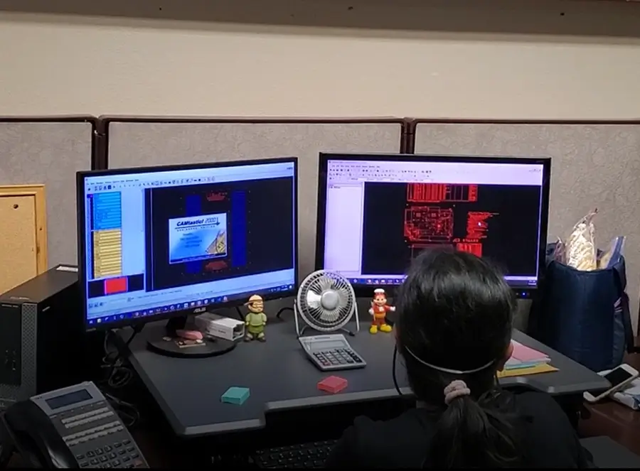
• Front End Engineering: Our Front End team reviews the submitted files for manufacturability. Send us your PCB Stackup or we can make a complimentary PCB Stackup for you!
Using our DFM (Design for Manufacturing) checklist, our Front End team checks for any violations like spacing and shorts. We ensure designs with HDI applications, impedance requirements, multiple laminations, and other high tech features, are ready for production. Our professionals work directly with you to sort out any concerns. Once our team has cleared your files as ready for manufacturing, the files are reviewed by our Quote team.
• Quoting: The New Hampshire based Gorilla quotation team manually reviews and quotes your design files. A PCB Fabrication quote will be sent to your email within 24 business hours. If your job includes Assembly, a dual quote for both PCB Fabrication and Assembly will be provided.
After the PCB Fabrication quote is accepted and the Purchase Order is complete, your assigned Gorilla Project Manager enters the order into an ERP system. Your Project Manager will be your main contact throughout the order process.
The ERP submission alerts Front End Engineering and production staff.
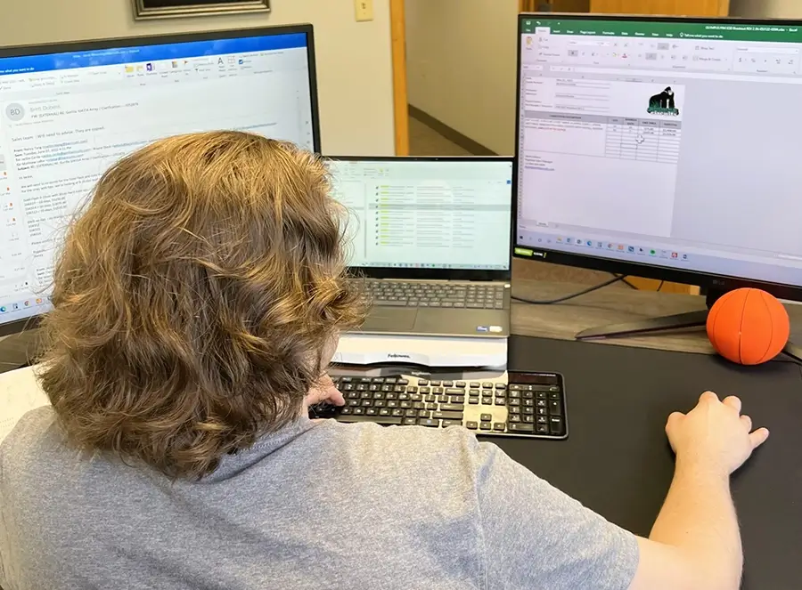
PCB Design data files are imported into CAM software. Gorilla staff standardize the file formats to allow for a smooth flow into production. Engineers review the design files and the Stackup in preparation for manufacturing, working directly with customers if questions arise.
PCB orders are typically made in panels. Panel sizes and the number of boards per panel are determined using internal software. Producing PCBs in panels optimizes the efficiency of the fabrication, allowing us to make more boards at once.
Now the job physically begins! All PCB Manufacturing occurs at our San Jose, California facilities.
In the Materials Department, rows of shelves store the most popular PCB Fabrication materials in a safe, climate controlled environment. Having these materials stored and ready for consumption expedites the build, preventing material acquisition delays.
Materials are issued by operators and cut.
Learn more about our Approved Materials below.
Copper laminate is mechanically and chemically pre-cleaned. This step cleans and prepares the core materials with a chromate protective layer.
Copper laminate is mechanically and chemically pre-cleaned. This step cleans and prepares the core materials with a chromate protective layer.
Using Laser Direct Imaging (LDI) technology, the circuit traces specified in the PCB Design are imaged onto each, individual PCB Inner layer. This special work takes place in a clean room where operators program the LDI machines. Inside the machines, a computer-controlled laser beam defines the circuit pattern onto each PCB inner layer.
Using Laser Direct Imaging (LDI) technology, the circuit traces specified in the PCB Design are imaged onto each, individual PCB Inner layer. This special work takes place in a clean room where operators program the LDI machines. Inside the machines, a computer-controlled laser beam defines the circuit pattern onto each PCB inner layer.
Gorilla operators use Automate Optical Inspection (AOI) machines to perform analysis on each, newly imaged PCB inner layer. Utilizing the PCB design as the model, the AOI machine scans the layers using laser sensors, electronically comparing the digital image with the original drawing. Every inner layer is examined to confirm an absence of defects prior to board creation.
Now that the inner layers have been imaged and verified, a Gorilla operator uses the Post Etch Punch machine on the corners of the PCB inner layers. These registration holes are punched so layers can be stacked evenly when the PCB Lay Up occurs in Step 8.
Time to build the board! In a process called “Lay Up”, the operator builds the board according to the PCB Stack Up specifications. Sheets of pre-preg laminate and PCB Inner Layers are alternated into a metal “book”. The holes created from the Post Etch Punch machine align into metal plate. When layers are properly stacked, a metal press plate is placed on top. The layers are secured so that the stack will not shift during pressurization. The stack of PCB layers is ready to be bonded into a board.
Time to build the board! In a process called “Lay Up”, the operator builds the board according to the PCB Stack Up specifications. Sheets of pre-preg laminate and PCB Inner Layers are alternated into a metal “book”. The holes created from the Post Etch Punch machine align into metal plate. When layers are properly stacked, a metal press plate is placed on top. The layers are secured so that the stack will not shift during pressurization. The stack of PCB layers is ready to be bonded into a board.
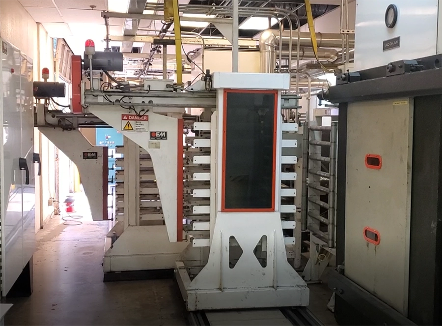
The metal book of PCB layers is placed inside an OEM press to fuse the layers into a board. Our computerized OEM Presses use heat pressurization to fuse the PCB layers into a solid board.
We have four OEM presses at our San Jose facility, enabling us to process multiple jobs at this stage at once.

The metal book of PCB layers is placed inside an OEM press to fuse the layers into a board. Our computerized OEM Presses use heat pressurization to fuse the PCB layers into a solid board.
We have four OEM presses at our San Jose facility, enabling us to process multiple jobs at this stage at once.
Removing the metal book from the OEM Press, a trained operator removes the press plate and pins binding the book. The PCB inner layers are now pressed into a solid board!
Removing the metal book from the OEM Press, a trained operator removes the press plate and pins binding the book. The PCB inner layers are now pressed into a solid board!
The new board is brought to the Drill Room, here the rough edge of the solid panel is cut into a clean, perfectly shaped edge.
The new board is brought to the Drill Room, here the rough edge of the solid panel is cut into a clean, perfectly shaped edge.
PCB Drilling establishes the foundation for vias and the connectivity between PCB layers. We offer high precision mechanical, laser, and X-Ray drilling. Our Drill Room features a 6-head Hitachi, two 6- head Schmoll Maschinen drills, and a Schmoll Maschinen X-Ray Drill. We also have several single panel drills, including five Hitachi Single Head Drills and three Schmoll Maschnin Single drills. Some jobs require a second Drill process run after Solder mask application (Step 15).
PCB Drilling establishes the foundation for vias and the connectivity between PCB layers. We offer high precision mechanical, laser, and X-Ray drilling. Our Drill Room features a 6-head Hitachi, two 6- head Schmoll Maschinen drills, and a Schmoll Maschinen X-Ray Drill. We also have several single panel drills, including five Hitachi Single Head Drills and three Schmoll Maschnin Single drills. Some jobs require a second Drill process run after Solder mask application (Step 15).
The Gorilla manufacturings facility features two new plasma etching machines. Plasma etching is an environmentally friendly, dry technique that thoroughly removes any epoxy resin that may have been left behind during the PCB drilling process. Plasma etching is the preferred etching technique for high-tech products. This is due to its ability to remove harder residues such as polyimides, Teflon, and RF Microwave materials.
The Gorilla manufacturings facility features two new plasma etching machines. Plasma etching is an environmentally friendly, dry technique that thoroughly removes any epoxy resin that may have been left behind during the PCB drilling process. Plasma etching is the preferred etching technique for high-tech products. This is due to its ability to remove harder residues such as polyimides, Teflon, and RF Microwave materials.
We offer manual and automatic Copper (Cu), Nickel (Ni), and Tin (Sn) plating.
PCB plating fills the drilled holes with copper to allow for the current to pass from the surface of the board to the inner layers, between layers, or between surfaces. This process involves a series of chemical baths that deposit thin layers of Cu (or other metals) on to the panels. Our chemical baths are under strict regulation that satisfy California’s progressive environmental standards.
In order to check for electrical discontinuities, we TDR test boards prior to solder mask application. Time Domain Reflectometers (TDR) use reflected waveforms to decipher the characteristic impedance of the PCB traces. Once the board passes the TDR test, solder mask application begins.
Solder mask adds a protective layer on the exterior surfaces of a printed circuit board, preparing the board for the eventual PCB Assembly soldering process. Solder mask essentially “masks” areas that don’t require soldering. In this process, ink epoxy and solder mask film are applied on to the surface. Once the Solder mask has been applied, the board is put into an oven to cure.
We offer a wide variety of Solder mask colors, the classic green to white, yellow, black, red, purple and blues! Specify in your PCB Design files what color you would like your PCBs to be.
We offer manual and automatic Copper (Cu), Nickel (Ni), and Tin (Sn) plating.
PCB plating fills the drilled holes with copper to allow for the current to pass from the surface of the board to the inner layers, between layers, or between surfaces. This process involves a series of chemical baths that deposit thin layers of Cu (or other metals) on to the panels. Our chemical baths are under strict regulation that satisfy California’s progressive environmental standards.
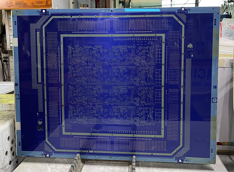

We offer various PCB surface finishes like Hasl/Hasl Lead-free, ENIG (Immersion Gold), ENEPIG (Electroless Nickel/Palladium Immersion Gold), Immersion Tin (ISn), and Immersion Silver (IAg).
The PCB surface finish coats the area between the metal face of the components and the pads on PCB. Coating protects the copper foil from oxidation and provides a surface for solder for the upcoming PCB assembly. Every PCB surface finish is customized per the requirements.
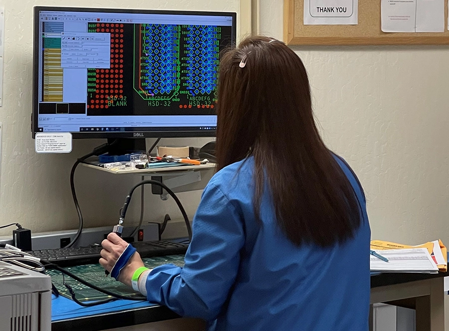
Electrical Testing is conducted on every new circuit board. Mandatory testing includes a Flying Probe Test, which assesses electrical connectivity on both sides of the board. Any shorts or defects found are flagged and addressed. All orders must pass the Flying Probe Test prior to shipment.
We house five Flying Probe Test machines, making electrical testing quick and easy!
Now that we know the boards are in working order, the PCBs are ready for final routing. Operators use machines to “cut” out the circuit boards from the panels in which they were created. These new bare PCBS are transformed into the single boards requested by the customer.
Now that we know the boards are in working order, the PCBs are ready for final routing. Operators use machines to “cut” out the circuit boards from the panels in which they were created. These new bare PCBS are transformed into the single boards requested by the customer.
In the final stages, the PCBs are analyzed by our Quality Control experts according to ISO 9001 and AS9100 standards.
A Micro Vu machine is used on certain high end or Class III jobs. This machine processes detailed measurements, proving the build is built exactly to specification. All data is sent to the customer.
Once all PCB inspections and quality checks are complete, the order is complete!
Depending on the job, the order is either passed on to our San Jose based PCB Assembly team or prepared for shipment.
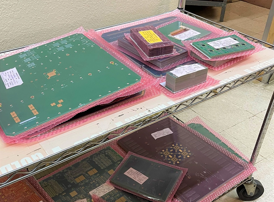
If this is a Fabrication only job, the PCBs are sealed safely in protective packaging. We use your preferred shipment method like Fedex, UPS, or DHL to ensure your PCB order is delivered as desired.
All shipment preferences should be shared with your Gorilla Project Manager assigned at the beginning of the order.